4.6 KiB
Kroki diagrams (CORE ONLY)
Introduced in GitLab 13.7.
When Kroki integration is enabled and configured in GitLab you can use it to create diagrams in AsciiDoc and Markdown documents.
Kroki Server
When Kroki is enabled, GitLab sends diagrams to an instance of Kroki to display them as images.
You can use the free public cloud instance https://kroki.io or you can install Kroki
on your own infrastructure.
After you've installed Kroki, make sure to update the server URL to point to your instance.
Docker
With Docker, run a container like this:
docker run -d --name kroki -p 8080:8000 yuzutech/kroki
The Kroki URL is the hostname of the server running the container.
The yuzutech/kroki image contains the following diagrams libraries out-of-the-box:
- Bytefield
- Ditaa
- Erd
- GraphViz
- Nomnoml
- PlantUML
- C4 model (with PlantUML)
- Svgbob
- UMlet
- Vega
- Vega-Lite
- WaveDrom
If you want to use additional diagram libraries, read the Kroki installation to learn how to start Kroki companion containers.
Enable Kroki in GitLab
You need to enable Kroki integration from Settings under Admin Area. To do that, log in with an administrator account and follow these steps:
- Select the Admin Area ({admin}) icon.
- Navigate to Settings > General.
- Expand the Kroki section.
- Select Enable Kroki checkbox.
- Enter the Kroki URL.
Create diagrams
With Kroki integration enabled and configured, you can start adding diagrams to your AsciiDoc or Markdown documentation using delimited blocks:
-
Markdown
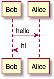
```plantuml Bob -> Alice : hello Alice -> Bob : hi ``` -
AsciiDoc
[plantuml]
....
Bob->Alice : hello
Alice -> Bob : hi
....
The above blocks are converted to an HTML image tag with source pointing to the Kroki instance. If the Kroki server is correctly configured, this should render a nice diagram instead of the block:
Kroki supports more than a dozen diagram libraries. Here's a few examples:
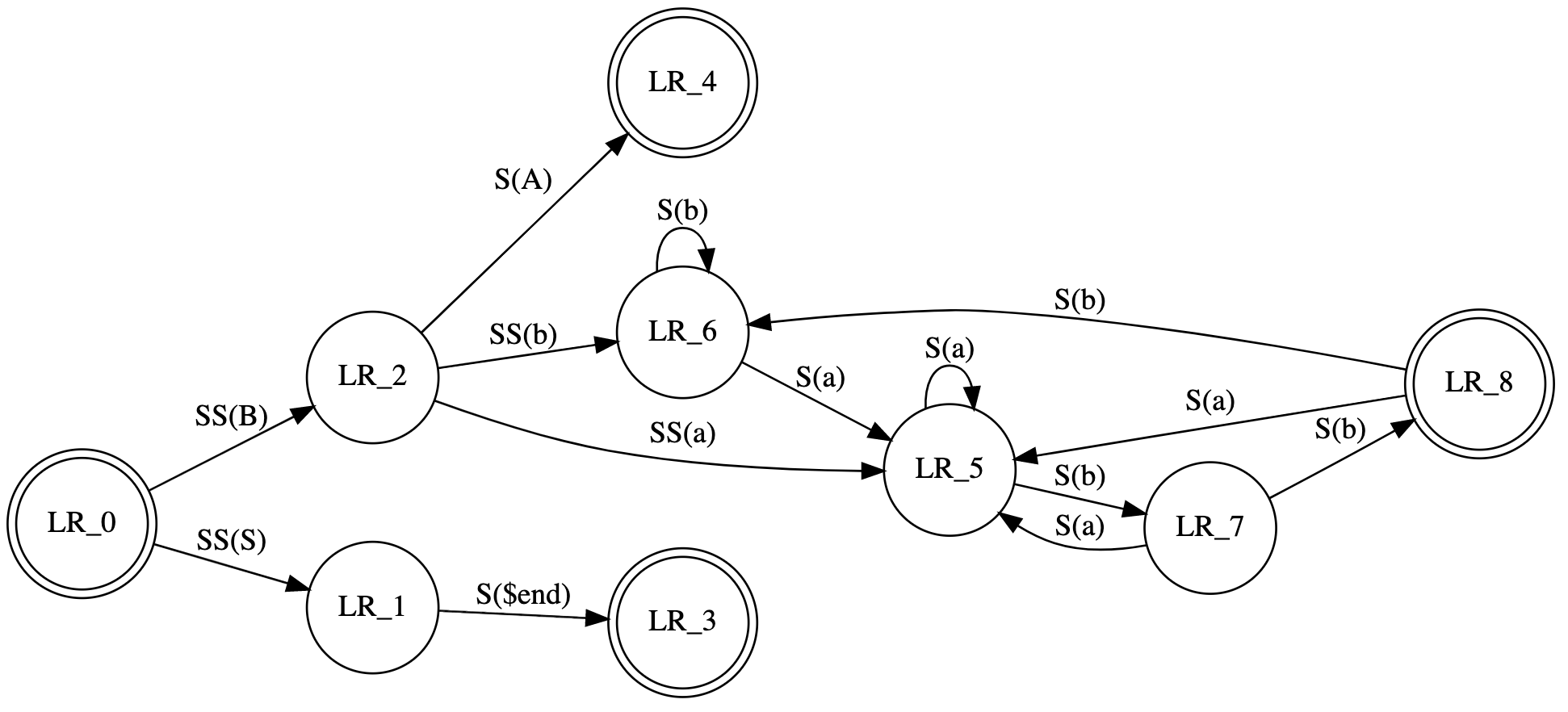
GraphViz
[graphviz]
....
digraph finite_state_machine {
  rankdir=LR;
  node [shape = doublecircle]; LR_0 LR_3 LR_4 LR_8;
  node [shape = circle];
  LR_0 -> LR_2 [ label = "SS(B)" ];
  LR_0 -> LR_1 [ label = "SS(S)" ];
  LR_1 -> LR_3 [ label = "S($end)" ];
  LR_2 -> LR_6 [ label = "SS(b)" ];
  LR_2 -> LR_5 [ label = "SS(a)" ];
  LR_2 -> LR_4 [ label = "S(A)" ];
  LR_5 -> LR_7 [ label = "S(b)" ];
  LR_5 -> LR_5 [ label = "S(a)" ];
  LR_6 -> LR_6 [ label = "S(b)" ];
  LR_6 -> LR_5 [ label = "S(a)" ];
  LR_7 -> LR_8 [ label = "S(b)" ];
  LR_7 -> LR_5 [ label = "S(a)" ];
  LR_8 -> LR_6 [ label = "S(b)" ];
  LR_8 -> LR_5 [ label = "S(a)" ];
}
....
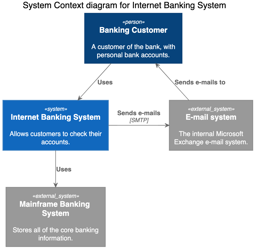
C4 (based on PlantUML)
[c4plantuml]
....
@startuml
!include C4_Context.puml

title System Context diagram for Internet Banking System

Person(customer, "Banking Customer", "A customer of the bank, with personal bank accounts.")
System(banking_system, "Internet Banking System", "Allows customers to check their accounts.")

System_Ext(mail_system, "E-mail system", "The internal Microsoft Exchange e-mail system.")
System_Ext(mainframe, "Mainframe Banking System", "Stores all of the core banking information.")

Rel(customer, banking_system, "Uses")
Rel_Back(customer, mail_system, "Sends e-mails to")
Rel_Neighbor(banking_system, mail_system, "Sends e-mails", "SMTP")
Rel(banking_system, mainframe, "Uses")
@enduml
....
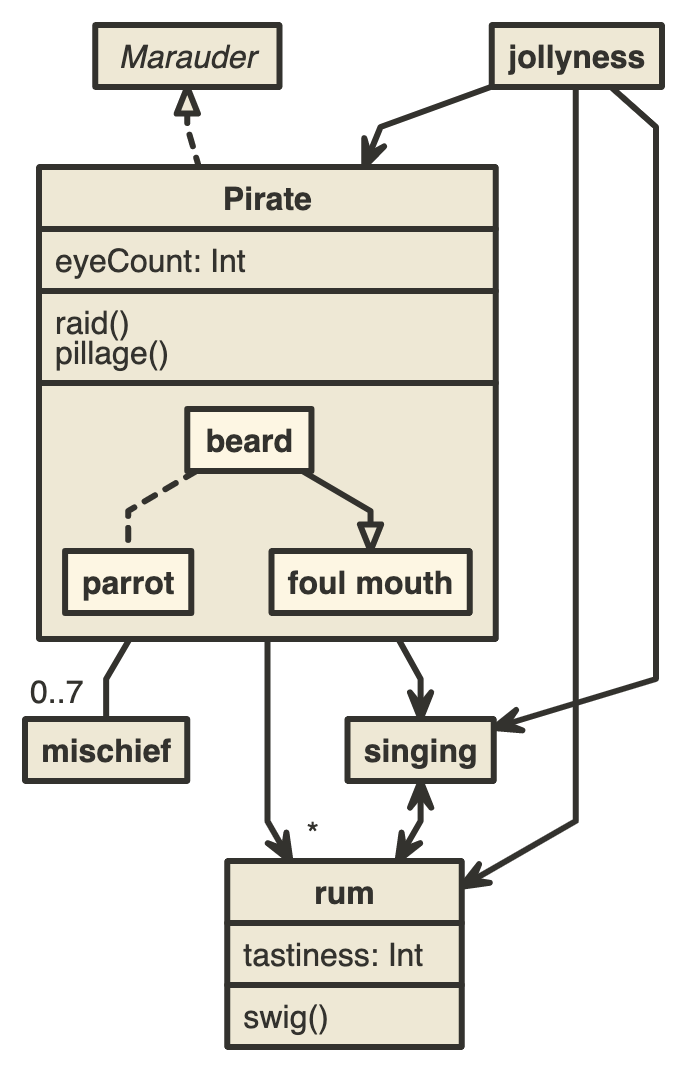
Nomnoml
[nomnoml]
....
[Pirate|eyeCount: Int|raid();pillage()|
  [beard]--[parrot]
  [beard]-:>[foul mouth]
]

[<abstract>Marauder]<:--[Pirate]
[Pirate]- 0..7[mischief]
[jollyness]->[Pirate]
[jollyness]->[rum]
[jollyness]->[singing]
[Pirate]-> *[rum|tastiness: Int|swig()]
[Pirate]->[singing]
[singing]<->[rum]
....


